
Trying to Explain QEMU in Simple Terms (Part 3):Peripheral
Introduction
In the previous article (Part 2), we explained machine code translation in QEMU, including Tiny Code Generator (TCG) and Translation Block (TB).
In this article (Part 3), we will explain the model of peripheral circuits in QEMU.
For Clarity: What is a Peripheral Circuit?
In the previous articles, we have frequently used the term “peripheral.” For clarity, we would like to confirm what “peripheral” refers to. Below is the block diagram of the microcontroller chip LM3S811, which uses the ARM Cortex-M3 CPU.
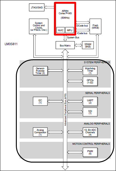
The red part in Figure 1 represents the ARM Cortex-M3 CPU. On the other hand, the circuits hanging off the bus within the black border, such as UART, Watchdog Timer, I2C, etc., are referred to as “peripherals.” “Peripheral” means “surrounding” or “external.” “Peripheral” is also called “peripheral circuits” or “external circuits.” Although not shown in the diagram, custom circuits connected to the bus, such as image processing circuits or AI processing circuits, can also be considered a type of “peripheral.”
MMIO(Memory-Mapped I/O)
In general, peripherals are referred to as MMIO (Memory-Mapped I/O). The term MMIO is also used in QEMU. The reason they are called MMIO is that peripherals are assigned addresses in the memory space as seen by the CPU. From the CPU’s perspective, peripherals are accessed using the same instructions as normal memory access (e.g., load or store).
IO stands for Input/Output and refers to the means by which the CPU interacts with external devices. It includes the following:
- Input: The CPU receives information from a device (e.g., keyboard input or reading sensor values).
- Output: The CPU sends information to a device (e.g., display output or sending control signals to a motor).
Peripheral Models Are Also C Functions
In QEMU, the behavior of peripheral circuits is also described as C functions. The program that this peripheral should execute is as follows:
- When the CPU writes a value to the initialization register inside the peripheral, the specified operation is executed.
- Once the operation is completed, an interrupt is sent to the CPU.
- It receives asynchronous events from external sources.
- Example: The UART receives an event from an external terminal.
Note that the term “asynchronous event” used above refers to an event that occurs at an unpredictable time. This can be understood as an event whose timing is not known in advance.
In a real machine, the CPU and each peripheral operate in parallel (simultaneously). However, QEMU is a program written in C, and it cannot express this parallelism. So, what QEMU does is periodically interrupt the execution of the converted machine code to perform the processing of the peripheral models.
We will explain how peripheral circuits are activated by the CPU in QEMU using Figure 2.
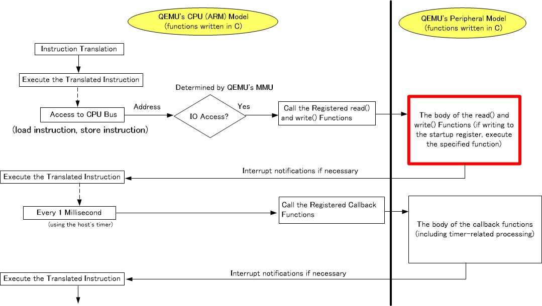
In Figure 2, when the converted machine code is executed and the instruction is a store instruction, QEMU’s MMU (Memory Management Unit) determines whether it is an I/O access or not. The MMU in QEMU will be explained in a later part of this series. The I/O here refers to peripherals. Even if it is a store instruction, if it is writing to DRAM, the peripheral model is not activated. However, if the destination address for the store instruction is a peripheral, the write() function defined in the corresponding peripheral model is called. Inside the write() function, if the destination address is the activation register, the peripheral’s operation (processing) will start.
Once the peripheral processing is complete (i.e., after the function execution finishes), the next instruction in the TB (Translation Block) (the converted instruction) will be executed. Afterward, if the CPU does not access the peripheral again, no further peripheral processing will take place. For example, in the case of UART, it must receive an event from an external terminal, the timing of which is unpredictable.
To avoid this issue, QEMU executes various pre-registered callback functions every 1ms. The 1ms interval is measured using the host’s timer. Additionally, the body of each callback function is defined within the corresponding peripheral model. Once the periodic processing is completed, QEMU then proceeds to execute the next instruction in the TB (Translation Block) (the converted instruction).
What if There is No C Model for the Peripheral?
If there is no QEMU C model for the peripheral that you want to use, the following solutions can be applied.
- Write the C model independently using C language
- It must be written according to QEMU’s conventions.
- With effort and by referring to existing peripheral models built into QEMU, it may be possible to do so.
- Write it using a C++ library called SystemC
- To use SystemC models in QEMU, a certain level of knowledge is required (Our company can also provide SystemC modeling).
- There may be pre-existing models for the desired peripheral in SystemC.
- Consult with us
- For information on our QEMU modeling services, please refer to the following.
Next Time
In this article (Part 3), we explained how peripherals are handled in QEMU.
In the next time (Part 4), we will explain address translation in QEMU. We will provide a detailed explanation of how the address spaces of the ARM CPU and x86 CPU are mapped to each other.