
Trying to Explain QEMU in Simple Terms (Part 2):First, Machine Code Translation
Introduction
In the previous article (Part 1), we introduced one of the usage scenarios of QEMU, where the host CPU is x86 and the guest CPU is ARM.
In this article (Part 2), we will explain how QEMU interprets and executes ARM CPU machine code on an x86 CPU.
What QEMU Needs to Do
The tasks QEMU needs to perform can be considered as follows:
- 1.Machine Code Translation
- Translate ARM CPU instructions into x86 CPU instructions.
- 2.Management of ARM CPU’s Internal Register States
- 3.Address Resolution
- Translate the ARM CPU (guest) address space into the x86 CPU (host) address space.
- 4.Peripheral Simulation
- Simulate the behavior of peripherals (UART, TIMER, etc.).
- 5.Support for Interrupts
We will explain each of these in detail below.
Machine Code Translation
First Method that Comes to Mind
How exactly does QEMU interpret and execute ARM CPU machine code on an x86 CPU? One possible approach that comes to mind is converting the entire ARM CPU binary file (executable) into an x86 CPU binary file using some method, and then executing the converted x86 CPU binary on the x86 CPU.
However, this approach would likely cause a significant problem. With this method, even if there is a small modification to the ARM program, the entire program would need to be converted again into an x86 CPU binary. This would be fine for small programs, such as one that simply displays “Hello World!”, but what if the executable is as large as ARM Linux? By the way, Linux, at its core, is just another C program.
If the ARM program is large, the conversion will take a significant amount of time. If the conversion only needs to be done once, it might be acceptable to spend time converting the entire program to x86, but if frequent modifications are made to the ARM program, this approach becomes impractical. Especially in embedded software development, changes are constantly made to the ARM program. Furthermore, converting the entire program just for a small change within a large program is clearly inefficient.
Repeat “Convert → Execute” step by step
QEMU does not convert the entire ARM CPU program into x86. Instead, it only converts the necessary parts of the ARM CPU program into x86 and executes them. For example, when booting an ARM CPU Linux, only the parts required for booting are converted to x86 and executed. To be more specific, QEMU advances the program counter on the ARM CPU step by step, converting one ARM CPU instruction into an x86 CPU instruction and executing it, then advancing the program counter again, converting, executing, and repeating this process. With this method, there is no need to convert the parts that are not executed.
However, performing “convert → execute” for each instruction incurs a certain cost (time) for QEMU. This is because QEMU itself uses an x86 CPU, so in order to execute the x86 instructions converted from the ARM CPU, it is necessary to first save the values of the registers and memory in the x86 CPU. Additionally, once the execution of the converted instruction is complete, the saved values of the x86 CPU’s registers must be restored from memory.
Since repeating “convert → execute” for each instruction is inefficient, QEMU performs conversion and execution in chunks of instructions. In QEMU, these “chunks” are defined by using jump instructions at machine code branch points and peripheral accesses as boundaries. The reason for using jump instructions and peripheral accesses as boundaries will be explained in another part of this series.
Additionally, it would be problematic if there were large “chunks” without jump instructions or peripheral accesses, so a size limit for these “chunks” is set in advance.
Now, let’s explain these “chunks.”
TB(Translation Block) and TCG(Tiny Code Generator)
In QEMU, each chunk separated by jump instructions is called a Translation Block (TB), and the part that converts this chunk (TB) into host code is called the Tiny Code Generator (TCG). The Tiny Code Generator is a C function that exists within QEMU. An overview of the Tiny Code Generator will be explained using Figure 1.
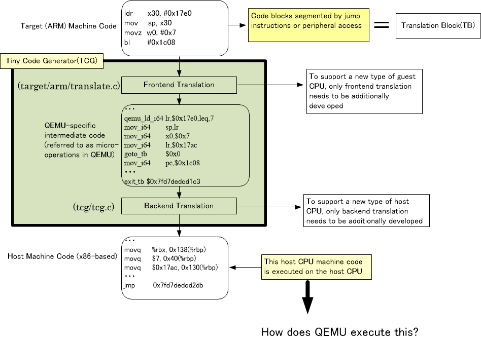
The part “target (ARM) machine code” in Figure 1 corresponds to the Translation Block (TB). Further explanation of Translation Block (TB) will be provided later. The green part in the diagram above represents the Tiny Code Generator.
As shown in Figure 1, the target (ARM) machine code is first converted into QEMU-specific intermediate code by the front-end translation part of the TCG (Tiny Code Generator). In QEMU, this intermediate code is called micro-operations. Roughly speaking, it is like an assembly language specifically designed for QEMU. This intermediate code is then converted into host (x86) machine code by the back-end translation part of the TCG (Tiny Code Generator).
Dividing the TCG into front-end and back-end translation has its advantages. For example, if you want to handle a new CPU, such as RISC-V, as the guest CPU, you only need to make the front-end translation part compatible with RISC-V, and without modifying the back-end translation, conversion from “RISC-V to x86” can be achieved. This is the reason for separating the front-end and back-end translation. This may be obvious, but I explained it just in case.
The problem is how QEMU executes the host (x86) machine code after it has been converted by the back-end. Since QEMU itself runs as an x86 program, it uses various registers in the x86 CPU. Given this, how does QEMU execute x86 machine code that has nothing to do with the QEMU program itself? If it were executed directly without any consideration, the values of the various registers used by the QEMU program in the x86 CPU would be overwritten, and this would cause the execution of the QEMU program to go wrong partway through.
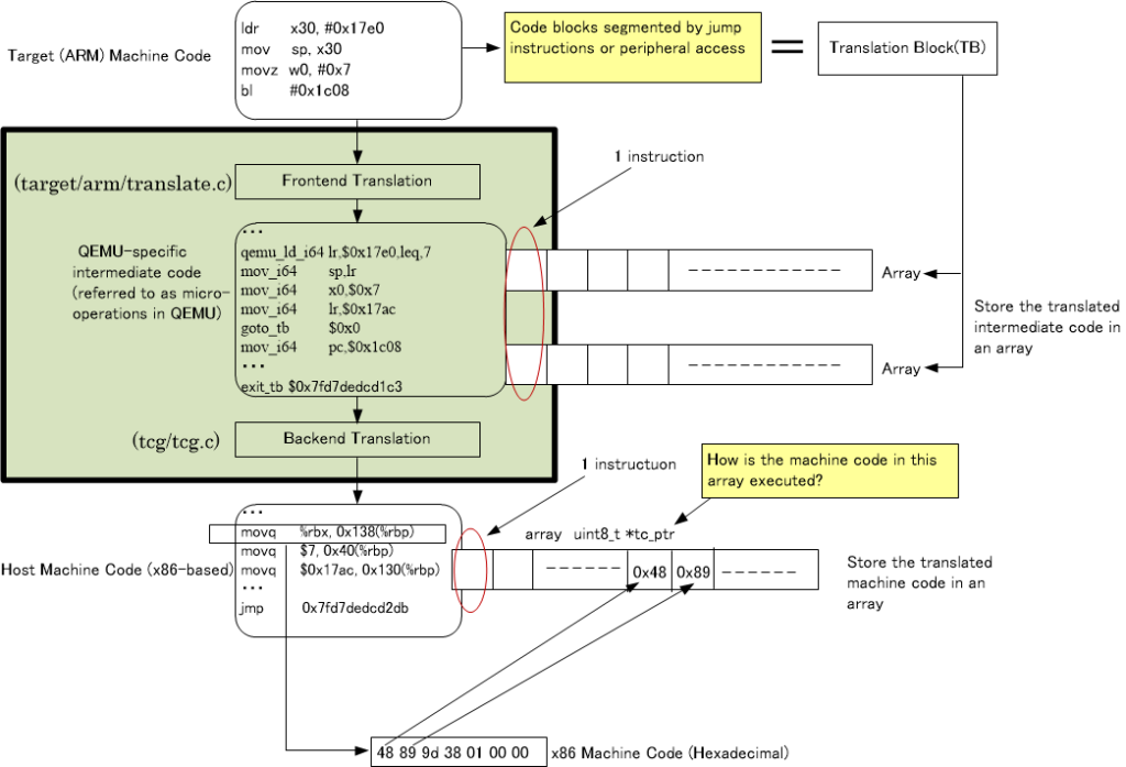
How to Execute Host (x86) Code
How is the host machine code generated by the TCG (Tiny Code Generator) executed on QEMU? As shown in Figure 2, the intermediate code from the front-end translation and the host machine code from the back-end translation for the extracted TB (Translation Block) are simply stored in an array.
QEMU executes the contents of the array generated by the back-end translation in the following way. It is quite complex, but let’s first display Figure 3.
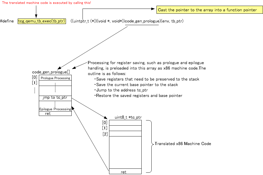
The variable tc_ptr shown in Figure 3 is the array that stores the x86 machine code generated by the back-end translation of the TCG. The central role in executing this machine code is played by the array code_gen_prologue, which appears in the diagram above. This array pre-stores the x86 machine code that performs the following actions:
- Save the various registers of the x86 CPU currently used by QEMU (This process is called the prologue in QEMU).
- Move the x86 program counter to the beginning of the tc_ptr array. After that, the program counter advances, and the x86 machine code stored in the tc_ptr array is executed. The reason the contents of the array can be executed is that this array is cast to a function pointer.
- After the execution of the converted x86 machine code is complete, restore the saved values of the x86 CPU’s registers from memory back to the x86 CPU’s registers (This process is called the epilogue in QEMU).
However, the array code_gen_prologue was removed from the QEMU source code in QEMU version 5.2.0 (released on October 28, 2020), and it seems that the approach has changed slightly. Nevertheless, for explaining the concept of QEMU, this explanation should still be accurate.
TB (Translation Block) is Reusable
The following information is stored as part of the TB (Translation Block):
- The memory address corresponding to the first instruction of the TB (program counter on the ARM CPU).
- The machine code after translation (stored in the array tc_ptr).
The first thing QEMU does when converting ARM CPU instructions to x86 CPU instructions is to check the value of the program counter (the address where the machine code to be converted is located) and see if there is a previously translated TB. If a previously translated TB exists, QEMU will skip the ARM to x86 conversion and execute the previously translated machine code (TB).
Continuous Execution of Translation Blocks (TB)
ARM CPU machine code programs are divided into Translation Blocks (TB) using jump instructions as boundaries. However, if there are few jump instructions, a single TB may become excessively large. To handle such cases, QEMU sets a maximum size for TBs in advance, and TBs are created using this size as the boundary.
Here, the execution of the first TB, TB1, is shown in Figure 4. The execution referred to here means the execution of the x86 instructions after conversion.
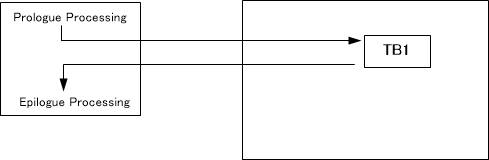
We assume that this TB1 is not divided by a jump instruction, but instead is divided by the maximum TB size.
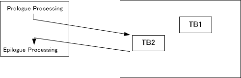
The execution of the second TB, TB2, is shown in Figure 5.
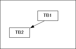
At this point, there is no jump instruction (conditional branch) between TB1 and TB2. Therefore, inside QEMU, TB1 and TB2 are remembered as a linked structure, as shown in Figure 6.
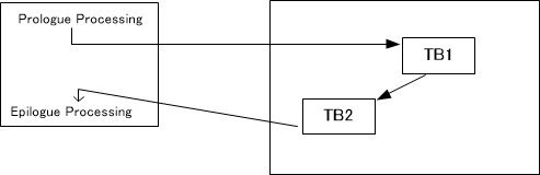
When executing TB1 again, as shown in Figure 7, the already converted TB1 is executed, followed by the continuous execution of TB2. No machine code translation takes place during the execution of TB1 and TB2 in sequence. The reason TB1 can be reused is that there are no jump instructions inside TB1. If there had been a jump instruction inside TB1, the behavior might be different from the previous execution, and the previous conversion result would not be applicable. This is the reason for dividing TBs at jump instruction boundaries.
A question that arises here is, “While it is true that TB1 and TB2 were executed consecutively last time, is it possible that a different instruction might be executed after TB1 this time?” However, since there are no jump instructions in TB1, it is guaranteed that the contents of TB2 will always be executed after TB1.
Continuous Execution of TBs Can Be Problematic
The previously mentioned continuous execution of TBs is beneficial as it eliminates unnecessary machine code translations. However, one issue arises. QEMU not only performs machine code translation but also needs to evaluate the C models of peripherals (such as UART) by checking for interrupts and other conditions. However, if TBs continue executing indefinitely, QEMU may lose the opportunity to perform these evaluations.
To address this, QEMU interrupts the machine code translation process and handles the peripheral C model (such as interrupt checks) using one of the following methods:
- A SIGNAL (Linux signal) is triggered every 1ms on the host side to interrupt the machine code translation process and handle the peripheral C model (such as interrupt checks).
- When using the -count option in QEMU (described later), the machine code translation process is interrupted once the maximum number of translation instructions is reached, allowing the peripheral C model to be processed (such as interrupt checks).
Which Instructions Can Be Represented in Intermediate Code? : Helper Functions
Not all ARM CPU machine instructions can be converted into intermediate code (QEMU-specific machine language). In cases where conversion into intermediate code is not possible, C functions are created. These are predefined as functions within the QEMU source code.
In QEMU, these functions are called helper functions. In the intermediate code, these helper functions are called.
ARM CPU Register Management?
When executing the converted x86 code, we discussed how the values of the various registers in the x86 CPU are saved during the prologue process.
On the other hand, the values of the various registers inside the ARM CPU are managed within QEMU’s C source code using the following structure.
typedef struct CPUARMState {
    /* Regs for current mode.  */
    uint32_t regs[16];

    /* 32/64 switch only happens when taking and returning from
     * exceptions so the overlap semantics are taken care of then
     * instead of having a complicated union.
     */
    /* Regs for A64 mode.  */
    uint64_t xregs[32];
    uint64_t pc;
    /* PSTATE isn't an architectural register for ARMv8. However, it is
     * convenient for us to assemble the underlying state into a 32 bit format
     * identical to the architectural format used for the SPSR. (This is also
     * what the Linux kernel's 'pstate' field in signal handlers and KVM's
     * 'pstate' register are.) Of the PSTATE bits:
     *  NZCV are kept in the split out env->CF/VF/NF/ZF, (which have the same
     *    semantics as for AArch32, as described in the comments on each field)
     *  nRW (also known as M[4]) is kept, inverted, in env->aarch64
     *  DAIF (exception masks) are kept in env->daif
     *  BTYPE is kept in env->btype
     *  all other bits are stored in their correct places in env->pstate
     */
    uint32_t pstate;
    uint32_t aarch64; /* 1 if CPU is in aarch64 state; inverse of PSTATE.nRW */

    /* Cached TBFLAGS state.  See below for which bits are included.  */
    uint32_t hflags;

    /* Frequently accessed CPSR bits are stored separately for efficiency.
       This contains all the other bits.  Use cpsr_{read,write} to access
       the whole CPSR.  */
    uint32_t uncached_cpsr;
    uint32_t spsr;

    /* Banked registers.  */
    uint64_t banked_spsr[8];
    uint32_t banked_r13[8];
・・・
Next Time
In this article (Part 2), we explained the machine code translation in QEMU and the execution of the converted machine code. By now, you should have a general understanding of what QEMU is and what happens inside QEMU during execution.
In the next time (Part 3), we will explain QEMU’s peripheral model.