
QEMU Modeling Service
We offer a modeling service that rapidly constructs virtual hardware models using QEMU. QEMU is an open-source CPU emulator that operates at high speed and supports various CPUs such as ARM and RISC-V. Here, we explain the features of our QEMU modeling service.
For a basic explanation of QEMU, please refer to our technical blog below.
Models Specialized in Interrupt Output
Issues with Virtual Hardware Models
Generally, virtual hardware models are used before the actual SoC (System On a Chip) is completed for purposes such as:
- Estimating SoC performance
- Accelerated development of software (embedded software) to control the SoC
Additionally, it is common to describe the behavior of CPUs like ARM or RISC-V and peripheral circuits in virtual hardware models using languages such as C/C++ or SystemC.
However, virtual hardware models have issues such as higher-than-expected costs and time for model development. Although they can be developed in a shorter period compared to actual hardware design like RTL design, they still require a considerable amount of work. If the development team is too small, the development period might end up being longer than that of RTL design, which is counterproductive. Additionally, knowledge of frameworks like SystemC or QEMU is necessary, increasing the barriers to modeling.
Focusing on Interrupts to Significantly Reduce Modeling Effort
Our QEMU modeling service has a significant feature: the models of peripheral circuits within the SoC (including user circuits) are specialized in interrupt output.
A model specialized in interrupt output might, for example, behave as follows:
“In peripheral circuit A, if the CPU writes to register B, an interrupt is output to the interrupt controller after 3ms.”
For instance, if the peripheral circuit is an image processing circuit, the detailed operations of the actual image processing are not modeled. Arbitration on the SoC bus is also not modeled.
Various conditions for outputting interrupts are modeled as necessary.
We believe that even such simple models specialized in interrupt output are useful in developing interrupt handlers and other aspects of SoC control software development.
Furthermore, by randomly generating interrupt outputs from the peripheral circuit model, it is possible to simulate hardware failures and observe the software’s behavior.
By specializing the virtual hardware model in interrupt output, it becomes possible to enable early development of software, as shown in the figure below.
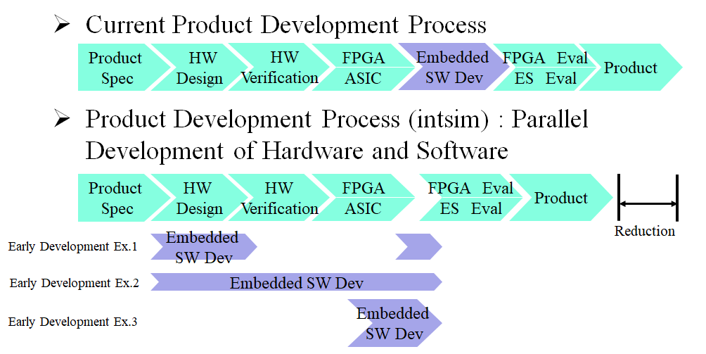
The reason why software development can be significantly accelerated is that the following information is sufficient for the development of a virtual hardware model for each peripheral (including user circuits). This information is considered to be available relatively early in the SoC development process.
- The base address of the peripheral
- Register information related to interrupt output within the peripheral circuit (e.g., offset addresses)
- Interrupt generation time (delay) information
Furthermore, by focusing on interrupt output, the model can be simplified, enabling rapid model development. While it is true that modeling only interrupt output may leave some aspects unverifiable in the software, there are still many aspects that can be verified.
Using QEMU as a Framework
Our virtual hardware models utilize QEMU as a framework. QEMU is an open-source CPU emulator that operates at very high speeds and supports various CPUs such as ARM and RISC-V. QEMU also allows for the modeling of peripheral circuits (peripherals).QEMU stands for “Quick Emulator,” and it is commonly pronounced as “Cue Emu,” though it is also referred to as “Kemu” in some cases. QEMU is “software” developed in the C programming language, and peripheral circuit models are also written in C, following the conventions of QEMU.
The usage image of QEMU is explained using Figure 2.
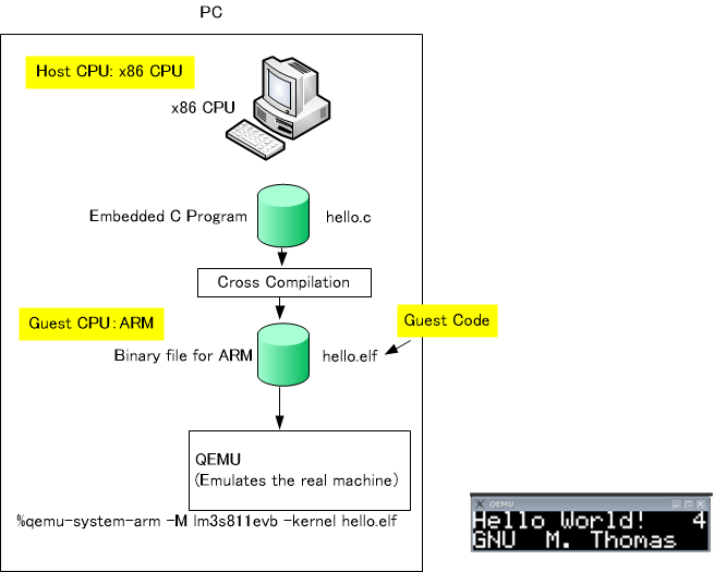
In Figure 2, a C source file named hello.c is created on an x86-based PC. After creating the C source file, cross-compilation is performed using an ARM GCC compiler, generating a binary file (executable file: ELF file) for ARM. Normally, this ELF file would be transferred to the actual hardware and executed on it. However, since the actual hardware is not available, the ELF file is passed to QEMU for execution. When the ARM-targeted ELF file is executed inside QEMU, the string “Hello World!” that should normally appear on the display of the actual hardware is instead displayed in a window on the PC (as shown in the bottom right of Figure 2).
In Figure 2, QEMU is executed as follows:
%qemu-system-arm -M lm3s811evb -kernel hello.elf
In the above command, qemu-system-arm is the QEMU main executable, and lm3s811evb corresponds to the name of the virtual hardware model. When we model virtual hardware for our customers, we provide the qemu-system-arm executable file and the C source code. Since qemu-system-arm is statically linked, customers can execute QEMU using just this file.
In this example, we have explained using ARM, but we are also capable of supporting other CPUs such as RISC-V.
As of now (November 2024), we support QEMU version 7.3.0 for Linux. We do not support the Windows version of QEMU.
Improving Model Development Efficiency with In-house Utility Tools
Even though the peripheral circuit models are specialized in interrupt output, manually creating C models for QEMU requires considerable knowledge and effort. To address this, we use an in-house GUI utility tool called “intsim” (Interrupt Simulator) to streamline QEMU modeling. Below, we introduce intsim in detail.
Features of intsim
The features of intsim are as follows:
- No need for C coding for QEMU modeling. Simply input various information in table format.
- Automates the process from generating QEMU models to executing QEMU.
- Easy to launch the simulator.
- Easy to launch the GUI source code debugger.
- Displays the state of interrupt outputs in a Gantt chart.
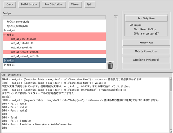
The main screen of intsim is shown below.
Structure of intsim
The overall structure of intsim is shown below.
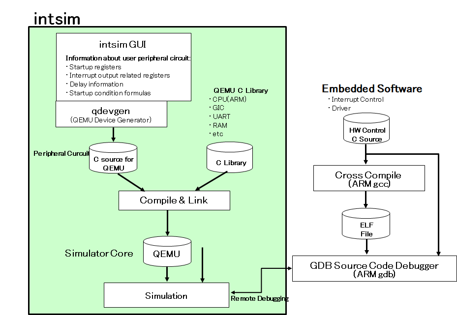
The “qdevgen” shown in the above figure is also a utility tool developed by our company.
Modeling Example Using intsim
The modeling process using intsim is as follows:
- 1.Define interrupt-related registers for each peripheral circuit (peripheral) using the GUI.
- 2.Define interrupt outputs for each peripheral circuit (peripheral) using the GUI.
- 3.Define the memory map: Set the base address of each peripheral circuit (peripheral) using the GUI.
- 4.Define the connections between peripheral circuits (peripherals) using the GUI.
- 5.Execute the simulation from the GUI.
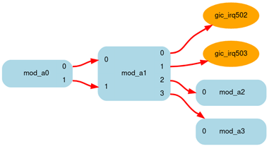
We will briefly introduce the GUI configuration screens for each of the above steps. The model used as an example is shown in the figure below. This figure is not related to the GUI of intsim but is simply created for explanatory purposes.
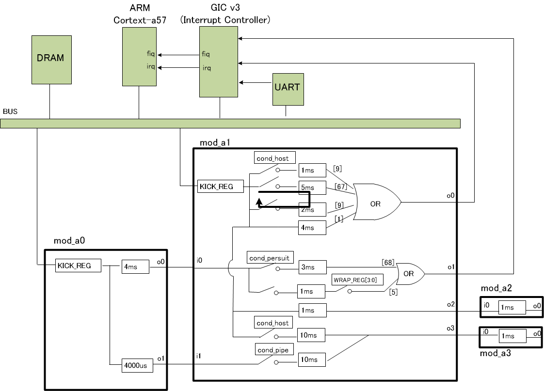
In our QEMU model, connections between peripherals are also implemented using QEMU’s interrupt mechanism. For example, the connection between the peripherals mod_a0 and mod_a1 in the above figure follows this approach.
Please note that there may be some differences between the GUI configuration screens shown below and the content of the above figure. However, we believe these examples will help you understand the overall concept of intsim.
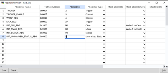
Definition of Interrupt-Related Registers
he following is an example of register configuration for the peripheral (mod_a1) in Figure 5.
Definition of Interrupt Output
The following is an example of interrupt output configuration for the peripheral (mod_a1) in Figure 5.
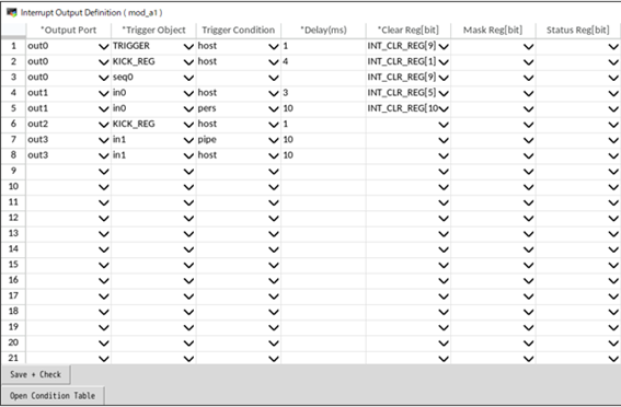
The above table contains a column titled “Trigger Condition,” where, for example, the word “host” is entered. This means that an interrupt will be triggered when the “host” condition is met. “Host” is a name given by the user for a condition they have defined, and this condition is specified in the condition definition table. The condition definition table is shown below.
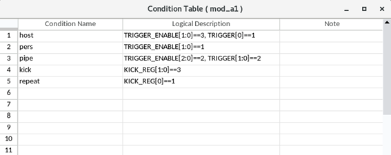
In the above condition definition table, the condition named “host” is assigned when the value of bits [1:0] of the register TRIGGER_ENABLE in mod_a1 is 3, and the value of bit [0] of the register TRIGGER is 1. The conditions are listed in a comma-separated format, and in the model, the AND operation is applied to the listed conditions.
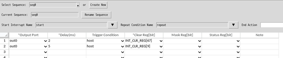
Definition of Interrupt Sequence
It is also possible to define an interrupt sequence for the interrupt output definition. An example of an interrupt sequence is:
“After interrupt A occurs, interrupt B occurs 2ms later, and after interrupt B occurs, another interrupt occurs 5ms later. After that, interrupts B and C repeat.”
It is also possible to define repetition conditions and register write definitions after the repetition ends.
The following is an example of an interrupt sequence definition for mod_a1 in Figure 5.
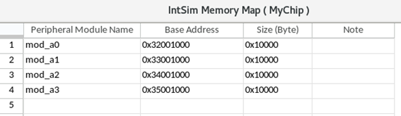
Memory Map Definition
The following is an example of a memory map definition configuration.
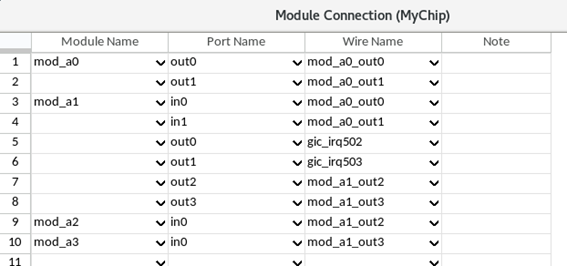
Definition of Peripheral-to-Peripheral Connection
The following is an example of a peripheral-to-peripheral connection definition.
After entering the above, it is also possible to display the block diagram shown below.
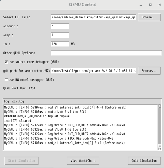
Running the Simulation
After entering the information in the GUI up to this point, you simply need to specify the ELF file in the window below and click the “Start Simulation” button to execute QEMU. Output to the UART will be displayed in the log window.
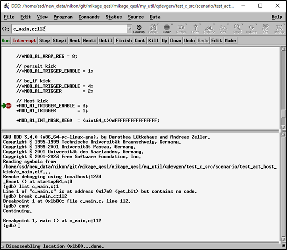
By checking “Use source code debugger (GUI)” in the above window, it is also possible to launch DDD as the GUI source code debugger, as shown below.
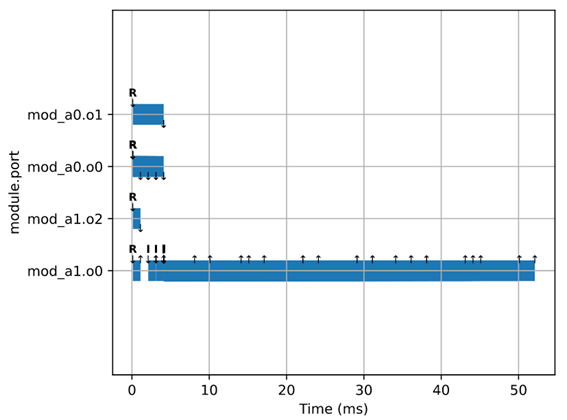
Additionally, after the simulation, it is also possible to display a Gantt chart showing the occurrence of each interrupt, as shown below.
Summary
We have introduced the development of interrupt output-specialized models in our QEMU modeling service. By focusing peripheral circuit models on interrupt output, models can be developed in a short period of time, enabling parallel development of software and hardware. If you are looking to start embedded software development as early as possible, we encourage you to consider using our QEMU modeling service.
Contact: qemu@profound-dt.co.jp